Kiss Esc Fc No Blue Light on Esc
In this tutorial we will explain the steps to update KISS 24A ESC v1.01, to newer firmware version. Also how to flash firmware in the KISS FC GUI Configurator.

We described briefly how to update firmware on the KISS 24A ESC before in our review. But it's slightly trickier for newer firmware like 1.03, as you first need to flash 1.02 to update the bootloader. The 1.02 bootloader allows you to flash future firmware via KISS FC GUI chrome app.
On v1.01, you cannot flash firmware using the GUI directly and that's why this whole process is required. That means we cannot flash 1.03 directly from 1.01 even with FTDI.
This tutorial is written by Artur Banach.
Tools Required
- USB to serial converter
- 3 x 1-Pin male to 1-Pin female servo wires
- XT60 wire with Crocodile clips + LiPo battery (for powering on the ESC)
Software needed
- Arduino IDE (I am using V1.05, newer version should also work)
- STM32 Flash loader demonstrator (UM0462) + necessary Windows drivers
Wiring
Before we start, it's a good idea to remove signal, telemetry and ground wires from the ESC, so there is no connection to the flight controller to avoid potential issues during the flashing process.
Depending on how you have your ESC installed on the quadcopter, you may need to de-solder them from the PDB to get easy access to the pads we need to connect to for the process.
If motors are still attached to the ESC make sure that the propellers are removed before the process.
Layout of the pads on KISS 24A ESC:
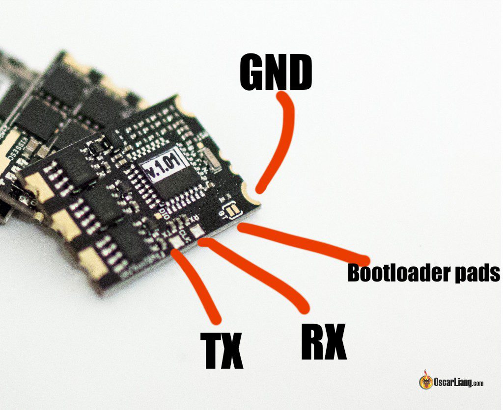
We only need RX, TX and GND outputs on serial converter:

Wires should be connected as follows:
- RX on serial converter to TX on ESC (red wire on the photo)
- TX on serial converter to EX on ESC (green wire on the photo)
- GND to GND (ground) on the ESC (blue wire on the photo)
I soldered the header pins on these pads.

Step 1 – Getting ESC Serial Number
Once you have connected the serial converter to the ESC as shown above, we can now connect the ESC to our computer, and get the serial number from it.
Plug the serial converter into the computer, and then power up the ESC using LiPo.
1 . Open Arduino IDE Software and go to Serial Monitor

2. In next window type 'info' and press ENTER (Make sure the 2 settings at the bottom are set correctly: Both NL & CRand 115200 Baud rate

3. You should see the ESC info appearing along with serial number (S/N):

4. Copy the serial number, and go to http://ultraesc.de/hexGen/index.php. Paste your serial number in the first text box

5. Press 'get hexfile' – a hex will be created and downloaded. We will need it to flash ESC in the next step
You can now disconnect ESC from the battery and computer.
Step 2 – Flashing boot loader to a newer version (1.02)
1 . Go to http://www.st.com/web/en/catalog/tools/PF257525 to download STM32 Flash loader demonstrator software:

2. Before connecting ESC to a computer, make sure you'veshorted Bootloader pads (BT). You can either solder it together or use a pencil to draw MANYlines crossing both pads (carbon is conductive). When the ESC is in bootloader mode, none of the LED's should be on when connected to power (LiPo). If you can still see LED lights up, it means it's not in bootloader mode yet.
3. Connect ESC to a computer and then power the ESC up.
4. Open STM32 Flash loader demonstrator, choose Baud Rate of 57600 and press next

5. There will be a message asking for 'Removing protection' , read the warning and click the the button:

Press ok here

Press Next here

6. On next window click Next

7. Choose your HEX file you have just downloaded. Make sure you select HEX extension from the filter. Select "Global Erase" and tick "Verify after download". After HEX was selected hit Open, then Next :


8. At this stage actual flashing commenced:

9. Verification in progress:

10. Flashing completed:

11. Now you can desolder boot loader pads (BT) or use rubber to remove the pencil traces :)
Summary
- You will have to repeat Step 1 and 2 for all the ESC's (because each ESC has a unique Serial Number therefore the hex files are unique)
- It might seem like a big task, but after all ESC's are flashed with the 1.02 bootloader, we can now flash ESC using KISS FC GUI app – which makes future ESC flashing much easier
Step 3 – Flashing ESC with KISS FC GUI
After we've completed Step 1 and 2 for all the ESC's, we can now flash newer ESC firmware (v1.03h) via KISS FC GUI without the need of soldering wires to ESC and using Serial Converter.
0. Solder your ESC's back to the FC and PDB first (which we previously had signal and ground removed from)
1 . Download the latest ESC firmware from http://kiss.flyduino.net
2. Connect to KISS FC without LiPo, press ESC Flasher in the top right corner:

3. A message will appear. Make sure read the warning, and that you actually understand what you are doing before pressing "I KNOW WHAT I AM DOING" :)

4. ESC flasher will open, and you can press SELECT FIRMWARE green button. Select your downloaded firmware hex file.

5. Connect LiPo to the quad – so that your ESC's are powered.
6. Click "FLASH FIRMWARE" and the process of flashing will begin. It will take a minute or two. During the process ESC LEDs will be flashing

7. A message will appear once the process is complete.

Congratulations, you've just updated your KISS 24A ESC to 1.03h :) . Time for a cup of tea and some biscuits :) or…your choice of favourite brewery – you've gone through the whole process, you need one.
What else do I need to know?
Any further ESC firmware updates can now be done using KISS FC GUI (after you have completed the above 3 steps).
You need to pay extra attention when doing this firmware update. Equipment can get damaged during the process. I was the perfect example, because when I was flashing one of my ESCs, the power wires snapped off and touched signal wire and shorted the ESC. I could only watch and smell the magic smoke before it hit the rubbish bin. :-(
Author: Artur Banach
Source: https://oscarliang.com/tutorial-kiss-24a-esc-firmware-upgrade/
Post a Comment for "Kiss Esc Fc No Blue Light on Esc"